ChipKIT Wi-Fire Pic32MZ Board Support Package (BSP) for Harmony

The Harmony programming software recommends the creation of a Board Support Package (BSP) for each development board so that basic board specific hardware like LEDs and Buttons can be defined in a single file which can be used across a range of Harmony Projects.

Below is the Board Support Package (BSP) I created for the ChipKIT Wi-Fire Pic32MZ Board.

1) Download the BSP Files:

BSP-pic32mz_Wi-Fire_V1.zip

2) Create a new BSP folder under C:\microchip\harmony\v1_02\bsp\ with the folder name pic32mz_Wi-Fire_V1.

The folder path should be adjusted for the version of Harmony being used (V1.2 assumed above).

3) Place the BSP files into the new folder

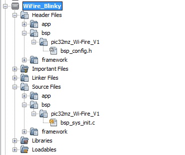
4) Add the Wi-Fire BSP folder to your MPLAB X Project.

BSP files included in a MPLAB X Harmony project.

Further details to be added….

Programming the ChipKit Wi-Fire via ICSP and PicKit 3

The ChipKIT Wi-Fire board comes pre-programmed with a bootloader which enables programmes to be transferred to it via the DIGILENT software available at www.digilentinc.com/wifire. This approach is recommended for beginners as a separate programmer is not required.


For intermediate users who wish to program the Wi-Fire using the free Microchip MPLAB X IDE and Harmony, a separate ICSP (In-Circuit-Serial-Programing) or JTAG programmer is needed.

The following article describes how to use the ICSP header provided on the Wi-Fire.

The ChipKIT Wi-Fire can be programmed via the ICSP (In-Circuit-Serial-Programing) header present on the board and located as shown below:

DSC00570-ICSP

The picture below shows the Microchip PicKit 3 connected to the ICSP header. The ICSP header on the board does not come with standard female header sockets but a standard 6-pin male header can be inserted into the board and hold in place sufficiently to program the board. It may be worth soldering on a 6-way female header if the reader is going to be programming the board frequently.

PickKit 3 connected to the ICSP port on the CHipKIT Wi-Fire Pic32MZ Board.
PicKit 3 connected to the ICSP port on the ChipKIT Wi-Fire Pic32MZ Board.

Note: The pin marked with a white triangle on the Pickit 3 connects to the pin marked “1” on the Wi-Fire ICSP header. The pin is also indicated by a square.

My Blog on the Pic32mz and ChipKit Wi-Fire

A site to share tips and code and ideas for the Pic32MZ.

I originally started on the Pic32MX when it was released but now couldn’t resist the Pic32MZ for the external memory interface and the High Speed USB. The ChipKit WiFire provides the ideal platform for prototyping.

My aspirations are:

  • Logic Analyser (Using the Higher Speed USB 2.0 to its maximum)
  • Logic Analyser (Using the SD card or external memory)
  • CMOS Camera interfaced to the PIC32MZ
  • DIY IP Camera (Wi-fi, Local SD Storage, Battery Power, PIR Motion sensor)